Determining the Beamwidth of a 60-cm Parabolic Antenna by Solar Transit on 3 November 2025
The 3-dB beamwidth (half-power beam width, HPBW) is a key parameter in radio astronomy as it determines the angular resolution of a radio telescope. It describes the angular range within which the received power rises to more than half its maximum value. The smaller the beamwidth, the higher the angular resolution of the antenna.
Setup and measurement method
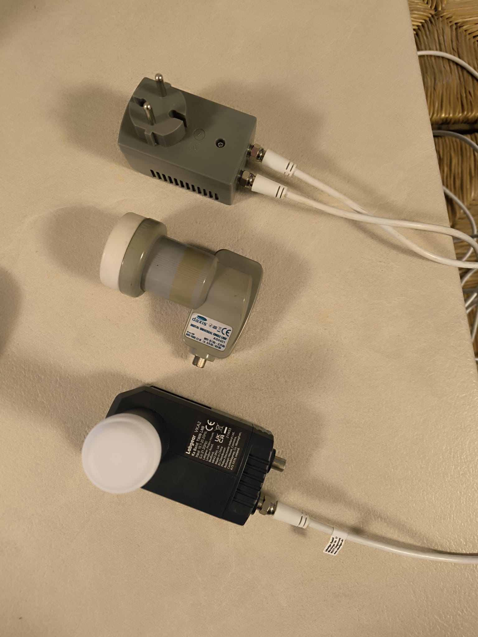
On 3 November 2025, the solar transit was measured with a 60-cm parabolic antenna at two frequencies: - 11.17 GHz using a Ku-band LNB - 19.78 GHz using a Ka-band LNB
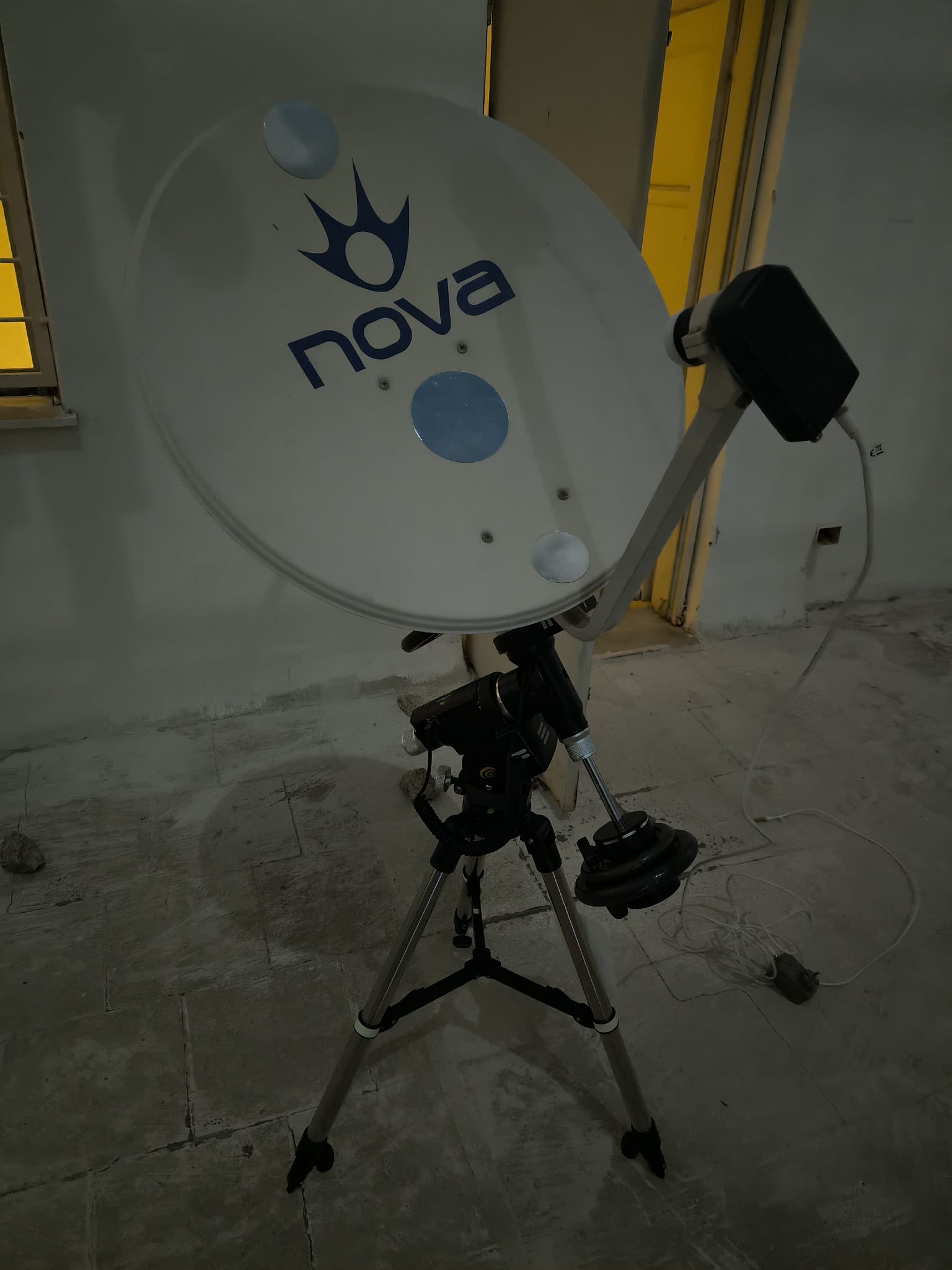
The antenna was installed on a PMC-8 iExos-100 equatorial mount, allowing the beam to drift across the solar position as Earth rotated. The receiver was a total-power detector (radiometer) with a 50 MHz bandwidth filter, whose output signal was recorded as a voltage trace during the transit.
The image shows the two transit curves for 11.17 GHz (blue) and 19.78 GHz (red) overlaid. The moments at which half the total power was reached (−3 dB points) and the maxima of the transit curves are also marked.
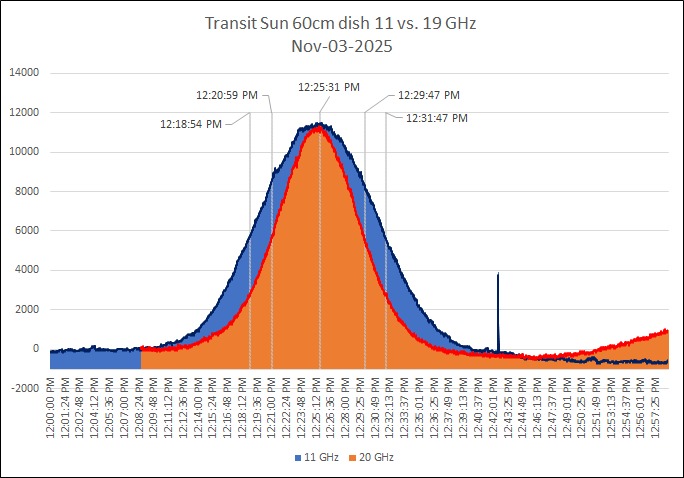
| Frequency | Transit time (−3 dB) |
|---|---|
| 11.17 GHz | 0 h 12 min 53 s |
| 19.78 GHz | 0 h 08 min 58 s |
Calculating the beamwidth from the drift time
Since the Sun drifts through the antenna beam during the measurement, the beamwidth can be determined directly from the transit duration. Earth rotates at an apparent angular velocity of
ω⊕ = 360° / 23h 56m 4s = 15.041°/h.
For a source at declination δ (on 03.11.2025: δ☉ = −15°) this gives
θ3dB = ω⊕ · t · cos(δ).
Calculation and results
- Calculation for 11.17 GHz:
t = 12.883 min = 0.2147 h θ11 = 15.041 × 0.2147 × cos(15°) = 3.11° After correction for the solar disc diameter (0.54°): θ11,corr = √(3.11² − 0.54²) = 3.06°
- Calculation for 19.78 GHz:
t = 8.967 min = 0.1494 h θ20 = 15.041 × 0.1494 × cos(15°) = 2.17° θ20,corr = √(2.17² − 0.54²) = 2.10°
| Frequency | Transit time | HPBW measured | HPBW corrected |
|---|---|---|---|
| 11.17 GHz | 12 min 53 s | 3.11° | 3.06° (184′) |
| 19.78 GHz | 8 min 58 s | 2.17° | 2.10° (126′) |
Comparison with theoretical values (aperture efficiency ≈ 55 %)
The theoretical beamwidth of a circular parabolic antenna is given by
θHPBW,th = k · λ / D,
where k depends on the illumination efficiency (aperture efficiency). For an efficiency of approximately 55 % (≈ −12 dB edge taper) the empirical value is k ≈ 1.17 rad = 67.1°.
Calculation:
| Frequency | λ (m) | λ/D | Theoretical (°) |
|---|---|---|---|
| 11.17 GHz | 0.0269 | 0.0448 | 67.1 × 0.0448 = 3.00° |
| 19.78 GHz | 0.01516 | 0.0253 | 67.1 × 0.0253 = 1.70° |
Discussion
The measured beamwidths of 3.1° (11 GHz) and 2.1° (19.8 GHz) are close to the theoretical expectations (3° and 1.7° respectively) for a 60-cm antenna with a realistic efficiency of between 50 % and 60 %. The somewhat larger measured value at 19.8 GHz still requires an explanation.